 audioknorz
ViFAST TQWT

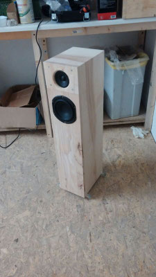
ViFAST Tapered Quarter Wave Tube - Small form factor Tower Speaker with homogenous dispersion and potent bass response
This project was born out of the ViFAST bookshelf size speakers elsewhere on this site. It's realised as a so called Tapered Quarter Wave Tube (TQWT). This type of enclosure nets an extended low frequency response with higher Q drivers while avoiding the boomy-ness which is often associated with using such drivers in a bassrelex cabinet.
ViFAST TQWT is a high value speaker with no real weaknesses but some conceptional strengths most conventional speakers can't offer. The low cost of around 65 Euro a piece (without cabinets) enables a cheap multi-chanal setup which fits it's excellent voice resproduction. It also plays music of all shades in a more than satisfactory manner.
Sounds to good to be true? Well there is one drawback. Building it, will be a bit more demanding than your usual two-way bookshelf, but will ultimately be worth it.
Tapered Quarter Wave Tube
The TQWT can be seen as a backloaded horn with a bass reflex port at it's end or a speacial form of a transmission line which widens towards it's outlet but than suddenly is constricted by an helmhotz resonator. Compared to it's TML relatives this enclosure type grants a better control over low and mid frequency resonances which result from the line geometry. To my knowledge currently there are just two tools (Leonardaudio Transmissionline, MJK Sheets which are sadly both currently not available online) that allow simulation of such an enclosure which is likely a reason for it's lower market penatration in the commercial sector compared to horns and transmissionlines.
Enclosure
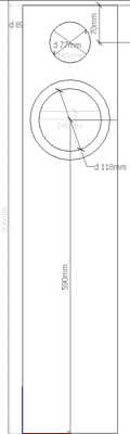
The enclosure is build from 16mm plywood, MDF or lesser density fibre woods. The wideband driver is located in a separted enclosure above the TQWT. Behind it's enclosure there is a a volume which is conected to the TQWT via a drilling hole with a diameter of 40mm. That volume acts as a helmhotz absorber, which dampens an unwanted line resonance around 280 Hz. For this to work it is imparative that the inside dimensions of this volume are as shown, and the material in which the hole is located has to be 16mm thick. The volume should be filled with around 20 gramms of PE based dampening material (we used "Sonofil" from Intertechnik).
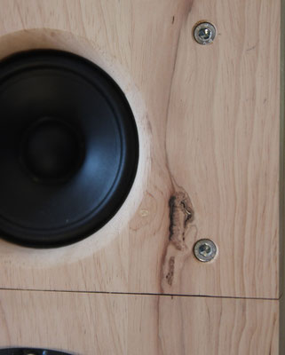
Please note, that the wideband driver has to be monted from behind into an 9mm deep radius for proper function. You can find details on the baffle construction in the original ViFAST article. To get to the driver later on we also recommend to make the top portion of the baffle removable.

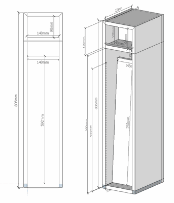

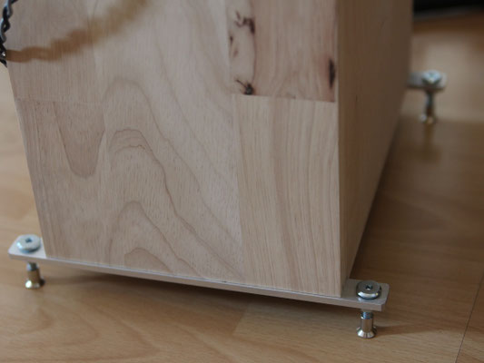
The port is mounted in the cabinets bottom. So some kind of Elevation from the ground is needed. You can just use spikes in the encolsure or build some crossbeams like we did and fit them with some bolts. The port has to have a 50 mm Diameter and should be trimmed to a length of around 8 cm. You can try different port lengths to accommodate for you room acoustics.

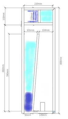
Dampening should be excuted as shown in the following illustration. Blue in this picture is compressed polyethelene foam from intertechnik.de called "Bondum 800". You can also use Eggcrate foam instead. If you can't get any of this, you can also try to compress standard PE-fill through the woofer opening after the cabinet has been glued together. Cyan is PE-Fill like Intertechnik's "Sonofil". Put this into the Helmhotz absorber's volume before you glue on the side wall, as you won't have access to this portion of the cabinet afterwards. Put it in there somewhat loosely, as a too tight filling will lowering the Q of the absorber's filtering function..
Filter and Measurements
The filter network is a slight variation from ViFast MK3 (bookshelf version). The adjustment was made to better accommodate to the now slightly less wide baffle.

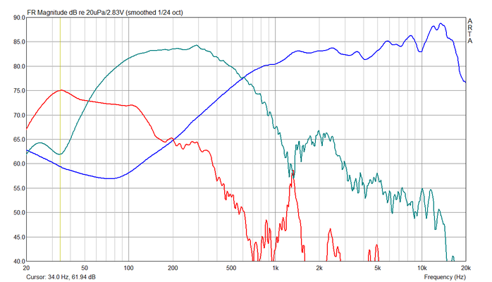
Frequency response in 1m in hight of the wideband driver without room reflections synthesized with LF near field (port and woofer under 200 Hz):

Mind that the port is in a downfireing position which makes the extended low frecquency response to be percieved louder than this measurement may make you suspect. This speakers will sound full and extended even in larger rooms.
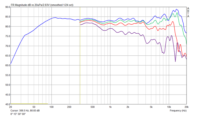
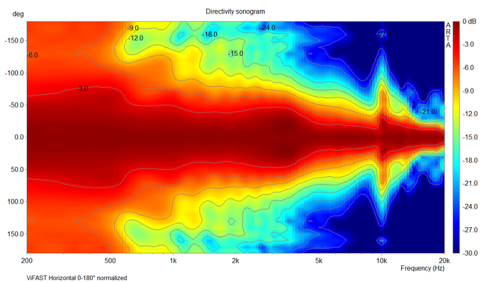
The following shows the measured horizontal and vertical polar response in form of sonogramms(*). The Image on the left shows the absolute sound pressure / energy radiation pattern while the right one is normalized to the zero degree angle.
Horizontal polar response:

Vertical polar response (negative values are up):


Especially the vertical dispersion is smooth in a manner that isn't possible with conventional multi-driver Speakers. It a result from it's crossover-point from LF to HF being low enough compared to the distance of both drivers for not causing huge phase differentials and therefore destructive inteference under angles.
The next graph shows the impedance of the speaker. The minimum lying around 5 ohms should be an easy task for virtually any amplifier.
Impedance:

* Please note, that the shown sonogramms are from the bookshelf version of ViFAST. It takes lots and lots of angle measurements to do this kind of graphs, which means hours and hours of work. There are only minor differences between the bookshelf and tower version of ViFAST above 200Hz. The resulting sonogramms should be very similar to virtually undistinguishable, which is why we deceided not to do them over. The conceptional differences should be clear anyway if the sonogramms are compared to those of convetional speakers elsewhere on this site.
Sascha Spee (Donnerstag, 28 Oktober 2021 22:19)
Hallo,
vielen Dank für die Mühe. Ich werde deinen Rat befolgen und es erst mal ohne Korrektur probieren.
Schönen Abend
Daniel (Admin) (Montag, 25 Oktober 2021 22:59)
Hallo Sascha,
also gemäß Simulation wäre ein LCR-Glied mit folgenden Bauteilen für den oberen Basshöcker passend:
L=
https://www.soundimports.eu/de/mundorf-p50-18.html
C=
https://www.soundimports.eu/de/mundorf-ecap63-270.html
R=
kann ich dir nicht genau sagen, dazu müsste ich die Modifikation aufbauen und messen.
Leider habe ich keine Kondensatoren in der Größe griffbereit, sonst würde ich etwas improvisieren. Aber du siehst, selbst mit den günstigen Bauteilen, erhöht sich das Budget schon mal ganz beträchtlich. Ich würde es erstmal ohne ausprobieren...
Sascha Spee (Freitag, 15 Oktober 2021 18:58)
Hallo,
da sag ich doch jetzt schon mal Danke für die Mühe! Da das Bauen auch noch eine Weile dauern wird ist auch keine Eile geboten.
Danke und schönes Wochenende
Daniel (Admin) (Donnerstag, 14 Oktober 2021 11:43)
Hallo Sascha,
Das 5ohm Minimum reicht nicht aus, um das Gerät als normgerechten 8ohm Lautsprecher auszuweisen, deswegen keine Gewähr für alle Röhrenamps :)
Zum Übertragungsverhalten: Ich denke die Schwankungen im Mittel und Hochtonbereich sollten sich nicht arg bemerkbar machen. Im Tieftonbereich wird es sicher zu einem leicht unterschiedlichen Klang im Vergleich mit einem Transistorverstärker kommen. Manchmal passt das auch ganz gut zur Raumakustik, aber das wäre auszutesten.
Ich muss mal nachgucken, ob ich damals ein Simulationsmodell angefertigt habe, dann könnte ich dir schnell einen Saugkreis / Imp.Korrektur für den oberen Bassbuckel basteln. Dazu werde ich aber erst in eins, zwei Wochen kommen!?
Sascha Spee (Donnerstag, 14 Oktober 2021 11:20)
Hallo Daniel,
ich will unbedingt die ViFAST TQWT nachbauen. Bin aber neu in der Dyi Szene und tu mich schwer die Diagramme zu deuten. Der Impedanzverlauf sieht im Vergleich mit vielen anderen Lautsprechern eher unkritisch aus. Dennoch die Frage, ob es für den Betrieb an einem Röhrenverstärker notwendig ist eine Impedanzkorrektur vorzunehmen. Falls ja, natürlich die nächste Frage ob es diese Impedanzkorrektur bereits gibt. Ich kann diese leider nicht selbst entwickeln.
Daniel (Admin) (Samstag, 15 Dezember 2018 10:59)
Zu meinem vorherigen Kommentar wäre noch zu ergänzen, dass eine Höhenbeschränkung (hier sollte eine einzige Leimholzplatte mit durchgehender Maserung als Front verwendet werden) auf ~80cm für das Gehäuse vorlag. Man kann das Tieftonabteil auch 2-3cm höher ausführen, wenn man bezüglich Kompression bedenken hat. Weitere Änderungen würde ich aber vermeiden.
Daniel (Admin) (Montag, 12 November 2018 08:04)
Hallo Michael,
erstmal Chapeau für die aufmerksame Frage ;) Die zwei cm Teilerlänge würden knapp 5cm Linelänge (nach der Timmermann'scher Berechnungsvorschrift) kosten. Ich wollte diesbezüglich möglichst nahe an der vorangehenden Simulation bleiben. Auch wenn die Fläche hier kurzzeitig verengt wird, glaube ich nicht, dass es zu großen Kompressionsverlusten kommt. Bei vielen TQWTs wird an dieser Stelle ja Sonofil über den Teiler gelegt, was zu deutlich größeren Verlusten führen dürfte. Aufgrund des sehr gut funktionierenden IHA's kann man sich das bei diesem Gehäuse sparen.
Ich würde den Lautsprecher eher als extrovertiert beschreiben, was den Bassbereich angeht. Von daher kann ich hier Entwarnung für etwaige Bedenken in diese Richtung geben.
VG Daniel
Michael Hohenberg (Samstag, 10 November 2018 15:19)
Hallo Daniel!
Ich verstehe eines nicht: Der Teiler der TQWT hat links und rechts ~ 10 cm Abstand zu den Wänden, oben sind es nur ~ 7 cm zur BB-Kammer und dem IHA. Ein Engpass in der TQWT. Warum ist das so?
Gruß Michael